
An automatic night light is a standard introductory project in embedded systems: an LED turns on when darkness falls and switches off when daylight returns. Yet building it reliably reveals the practical gap between simple textbook schematics and robust firmware engineering.
A photoresistor outputs no voltage on its own. Pair it incorrectly in a voltage divider, and your microcontroller reads a flatline. Set a single threshold in code, and the lamp repeatedly switches on and off as evening light settles.
In this tutorial, you will design, simulate, and verify an Arduino-based automatic night light using CircuPilot. Instead of hand-drawing every wire, you can prompt the AI to generate the complete schematic and firmware, inspect the circuit, adjust light levels interactively, and verify that software hysteresis reduces repeated switching caused by small changes or noise near a single threshold.
You can also test the live, interactive circuit directly in your browser: open the shared Arduino LDR night light simulation.
The Core Concept: Converting Light into Voltage
An LDR (light-dependent resistor, or photoresistor) changes its electrical resistance based on ambient illumination. Photons striking the semiconductor surface release charge carriers into the conduction band, lowering device resistance. In deep darkness, resistance climbs dramatically into hundreds of thousands of ohms.
Because an Arduino analog pin measures voltage (0 to 5 V) rather than resistance, the LDR must be placed inside a voltage divider:
+5V ──[ LDR (GL5528) ]──┬──[ 10 kΩ Resistor ]── GND
                        │
                     Pin A0
With the LDR on the high side (connected to +5V) and a fixed 10 kΩ resistor pulling down to ground:
1. In bright daylight: The LDR resistance drops below 1 kΩ. The 10 kΩ pull-down resistor dominates the divider, pulling the A0 junction close to 5 V (high analogRead value).
2. In darkness: The LDR resistance climbs above 50 kΩ. Most of the 5 V drops across the LDR, pulling node A0 down toward ground (low analogRead value).
For a detailed analysis of swapping the sensor position to ground, see our guide on which way round your divider goes.
Modeled Voltage and ADC Readings
CircuPilot models the photoresistor based on the standard GL5528 relationship R_LDR = R₁₀ × (10 / lux)^0.7, using a 10 kΩ reference resistance at 10 lux. Physical photoresistors have wide manufacturing tolerances (often ±30% or more) and temperature drift, but this mathematical model provides a consistent baseline for circuit analysis.
The calculated behavior of the 5 V divider across different modeled illumination levels is shown below:
| Environment | Modeled Lux | Calculated LDR Resistance | Modeled Voltage at A0 | Theoretical 10-bit ADC Count |
|---|---|---|---|---|
| Bright room / daylight | 1,000 lx | ~398 Ω | 4.81 V | ~984 |
| Well-lit interior | 100 lx | ~2,000 Ω | 4.17 V | ~853 |
| Dim room / sunset | 10 lx | ~10,000 Ω | 2.50 V | ~512 |
| Twilight transition | 4 lx | ~19,000 Ω | 1.72 V | ~353 |
| Deep twilight | 2 lx | ~30,900 Ω | 1.22 V | ~250 |
| Moonlight / dark room | 1 lx | ~50,100 Ω | 0.83 V | ~170 |
| Pitch darkness | 0.1 lx | ~251,200 Ω | 0.19 V | ~39 |
The modeled midpoint (2.50 V, ADC count 512) lands at 10 lux, where the LDR matches the 10 kΩ fixed resistor. This makes 10 kΩ a useful reference value for this modeled illumination range.
Step 1: Generate the Circuit with AI
Open the CircuPilot Simulator and type your prompt into the AI prompt bar:
AI Prompt:
"Arduino Uno automatic night light with an LDR sensor on analog pin A0 with a 10k pull-down resistor, and an LED on digital pin 13 with a 220 ohm current-limiting resistor."
Within seconds, the platform synthesizes:
- An Arduino Uno microcontroller board (
mcu_arduino_uno). - A photoresistor (
LDR1) wired between +5V and analog pin A0. - A 10 kΩ pull-down resistor (
R1) from A0 to ground. - An external red LED (
D1) wired to digital pin D13 with an external series 220 Ω resistor (R2) to limit forward current. While physical Uno boards feature a tiny built-in surface-mount LED on pin 13 with an onboard resistor, an external discrete LED wired on a schematic requires its own current-limiting resistor (see what resistor to use for an LED). - The complete Arduino C++ firmware loaded in the integrated code editor.
Step 2: The Firmware and Software Hysteresis
A common pitfall in sensor control code is relying on a single comparison threshold:
// Flawed approach: prone to repeated switching!
if (analogRead(A0) < 300) {
  digitalWrite(13, HIGH);
} else {
  digitalWrite(13, LOW);
}
If the sensor reading fluctuates around a single switching threshold (due to analog sensor noise or small ambient shifts), the LED may switch repeatedly on and off.
Software hysteresis (a Schmitt trigger implemented in code) reduces repeated switching caused by small changes or noise near a single threshold by separating the turn-on and turn-off points:
- Turn ON only when the ADC reading falls below 250 (approximately 2 lux in this model).
- Turn OFF only when the ADC reading rises above 350 (approximately 4 lux in this model).
- Within the deadband between 250 and 350, the firmware retains its previous state.
Here is the complete Arduino sketch:
/*
 * Automatic Night Light with Software Hysteresis
 * CircuPilot Circuit Simulator
 */

const int SENSOR_PIN = A0;
const int LED_PIN = 13;

// Hysteresis thresholds (ADC 0-1023)
const int THRESHOLD_DARK  = 250;  // Turn ON when ADC reading falls below 250 (~2 lx in this model)
const int THRESHOLD_LIGHT = 350;  // Turn OFF when ADC reading rises above 350 (~4 lx in this model)

bool lightIsOn = false;

void setup() {
  pinMode(LED_PIN, OUTPUT);
}

void loop() {
  int sensorValue = analogRead(SENSOR_PIN);

  // Evaluate state with hysteresis deadband
  if (!lightIsOn && sensorValue < THRESHOLD_DARK) {
    lightIsOn = true;
    digitalWrite(LED_PIN, HIGH);
  } else if (lightIsOn && sensorValue > THRESHOLD_LIGHT) {
    lightIsOn = false;
    digitalWrite(LED_PIN, LOW);
  }

  delay(100);
}
Step 3: Interactive In-Browser Simulation
Click the Run button on the workspace toolbar.
CircuPilot compiles your C++ sketch to machine code using arduino-cli and boots an in-browser cycle-accurate AVR emulator (avr8js). For more background on how embedded code executes in the browser without hardware, see how to simulate an Arduino circuit online without hardware.
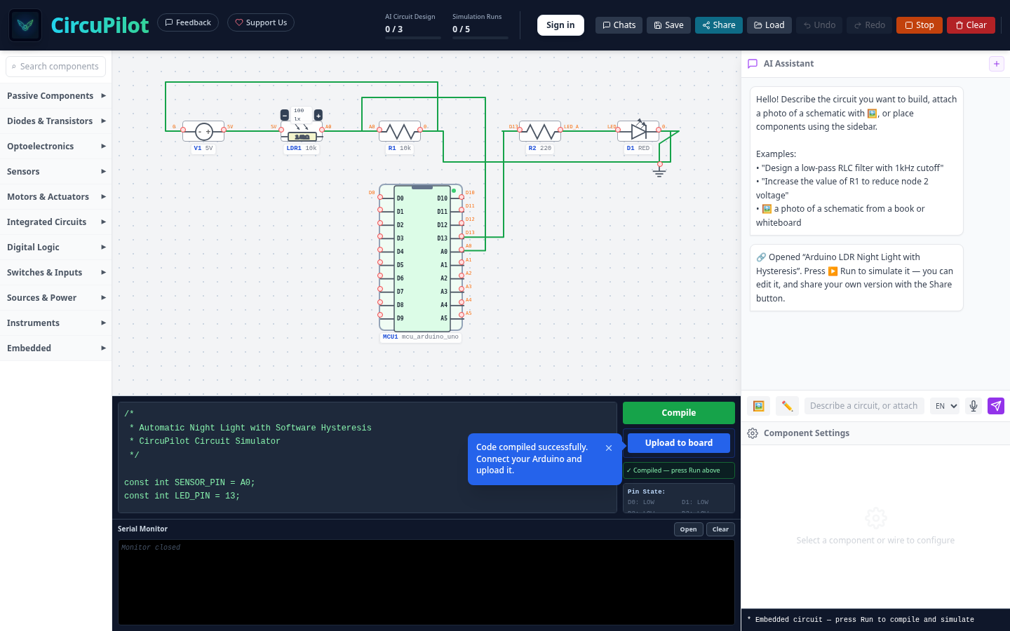
When simulation begins:
1. At default room lighting (100 lx), the modeled node voltage at A0 sits near 4.17 V (ADC ~853). The external LED remains completely off.
2. Click the − step button directly on the LDR canvas component to reduce illumination through 50 lx, 25 lx, 13 lx, and 4 lx (a continuous illuminance slider is also available in the component inspector sidebar).
3. Once the light level drops to 1 lx (ADC reading ~170, falling below our 250 threshold), the AVR emulator executes digitalWrite(13, HIGH), driving pin D13 high and illuminating the red LED on the schematic.
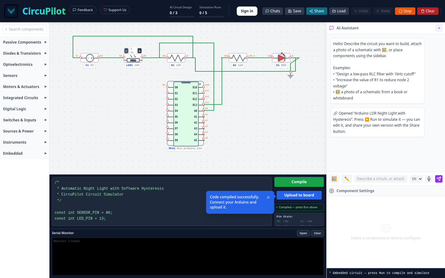
Now test the hysteresis deadband by increasing light:
- Click the
+button to step light back up to 2 lx and 4 lx: the LED stays lit, because the turn-off condition requires the ADC reading to rise above 350 (above 4 lux). - Step up to 7 lx: the ADC reading comfortably exceeds 350, and the LED switches off.
- Step back down into the 2–4 lx range from the bright side: the LED remains off until light drops past the 250 turn-on threshold once again.
Step 4: Share or Flash to Physical Hardware
When your design is complete, you can use it beyond the simulator workspace:
- Share your simulation: Generate a permanent link to share your exact circuit layout and firmware with colleagues or students (see how to share a circuit simulation link). You can explore this working example directly at app.circupilot.com/c/ExNTrRPG.
- Upload to physical hardware: In Web Serial compatible desktop browsers (Chrome and Edge), you can select Upload to board to flash the compiled binary directly to a connected Arduino Uno or Nano (ATmega328P) over USB without leaving the browser or opening the Arduino IDE.
Frequently asked questions
Why does an LDR need a fixed resistor to work with an Arduino?
An LDR is a variable resistor, not a voltage generator. Microcontroller analog inputs measure voltage (0 to 5 V), not raw resistance. By pairing the LDR with a 10 kΩ fixed resistor in a voltage divider, changes in ambient light produce measurable voltage swings at the ADC pin.
Why does an automatic night light flicker near its switching point?
When ambient light hovers around a single threshold, sensor noise or small light shifts cause the ADC reading to cross the boundary repeatedly, making the LED switch rapidly on and off. Software hysteresis prevents this by using separate turn-on and turn-off thresholds.
Which pin does the LDR divider connect to on an Arduino Uno?
In a standard divider configuration, the junction between the LDR and the fixed resistor connects to an analog input pin, commonly pin A0.
What happens if the LDR and fixed resistor swap positions?
If the LDR connects to +5V and the fixed resistor to GND, the junction voltage rises with light and falls in darkness. Swapping them makes the voltage rise in darkness and fall with light. Both arrangements work, but the firmware comparison logic must match your specific wiring.