
In digital systems, comparing two binary numbers is a foundational combinational operation. Whether a microcontroller evaluates a conditional branch instruction (if (A > B)), an arithmetic logic unit (ALU) updates comparison flags, or a peripheral controller performs memory address decoding, digital hardware must determine which of two binary words is larger, smaller, or whether they are equal.
A magnitude comparator is a combinational circuit designed specifically for this task. Unlike an arithmetic subtractor that computes the quantitative numerical difference (A − B) along with multi-stage carry and borrow propagation, a comparator evaluates relative magnitude directly through parallel logic paths, minimizing overall gate levels.
Following our guide on building a 4-bit binary adder with logic gates, this tutorial details the architecture, Boolean derivation, and SPICE simulation of an unsigned 2-bit magnitude comparator. We construct the complete 16-row truth table, examine gate counts and propagation paths, and verify every state interactively in your browser.
You can launch and test the verified pre-wired circuit directly in your browser:
---
1. What Is an Unsigned Magnitude Comparator?
An unsigned magnitude comparator takes two binary numbers, A and B, and asserts exactly one of three active-HIGH digital output lines:
GT(A > B): High (approx 4.99 V) when unsigned numberAis strictly greater than unsigned numberB.EQ(A = B): High (approx 4.99 V) when unsigned numberAis identical to unsigned numberB.LT(A < B): High (approx 4.99 V) when unsigned numberAis strictly less than unsigned numberB.
Steady-State Mutual Exclusivity
Once input signals have propagated through the gates and the circuit reaches steady-state equilibrium, exactly one relationship must hold true:
GT + EQ + LT = 1
Furthermore, no two outputs can remain active simultaneously in steady state:
GT · EQ = 0, GT · LT = 0, EQ · LT = 0
Dynamic Hazards and Transient Glitches
It is important to distinguish steady-state logic from dynamic switching. Because signals traveling along different gate paths experience slightly different propagation delays (for example, the MSB product term travels through fewer gates than the gated LSB term), brief transient transitions called glitches or hazards may appear on output pins during input transitions (such as changing from 01 to 10). These nanosecond glitches are normal combinational circuit phenomena and settle rapidly into the mutually exclusive steady state.
---
2. Input Bit Representations (Unsigned Binary)
In this circuit, both inputs are treated as pure unsigned binary numbers:
- Number A:
A = (A₁, A₀), whereA₁is the Most Significant Bit (weight 2) andA₀is the Least Significant Bit (weight 1). The decimal magnitude isA = 2 · A₁ + A₀, representing values from0to3. - Number B:
B = (B₁, B₀), whereB₁is the Most Significant Bit (weight 2) andB₀is the Least Significant Bit (weight 1). The decimal magnitude isB = 2 · B₁ + B₀, representing values from0to3.
Because there are 4 independent binary inputs (A₁, A₀, B₁, B₀), there are 2⁴ = 16 distinct input combinations.
---
3. Complete 16-Row Truth Table (SPICE-Verified)
The table below lists every input vector, its decimal conversion, the mathematical relation, and the measured steady-state DC operating point voltages from CircuPilot's ngspice simulation. The simulated HIGH level settles at 4.99 V across the terminal 100 kΩ pull-down resistors, while LOW settles at 0.00 V:
| Row | A₁ | A₀ | B₁ | B₀ | Decimal A | Decimal B | A > B (GT) | A = B (EQ) | A < B (LT) | Condition | Steady State |
|---|---|---|---|---|---|---|---|---|---|---|---|
| 1 | 0 | 0 | 0 | 0 | 0 | 0 | 0.00 V | 4.99 V | 0.00 V | A == B | Active EQ |
| 2 | 0 | 0 | 0 | 1 | 0 | 1 | 0.00 V | 0.00 V | 4.99 V | A < B | Active LT |
| 3 | 0 | 0 | 1 | 0 | 0 | 2 | 0.00 V | 0.00 V | 4.99 V | A < B | Active LT |
| 4 | 0 | 0 | 1 | 1 | 0 | 3 | 0.00 V | 0.00 V | 4.99 V | A < B | Active LT |
| 5 | 0 | 1 | 0 | 0 | 1 | 0 | 4.99 V | 0.00 V | 0.00 V | A > B | Active GT |
| 6 | 0 | 1 | 0 | 1 | 1 | 1 | 0.00 V | 4.99 V | 0.00 V | A == B | Active EQ |
| 7 | 0 | 1 | 1 | 0 | 1 | 2 | 0.00 V | 0.00 V | 4.99 V | A < B | Active LT |
| 8 | 0 | 1 | 1 | 1 | 1 | 3 | 0.00 V | 0.00 V | 4.99 V | A < B | Active LT |
| 9 | 1 | 0 | 0 | 0 | 2 | 0 | 4.99 V | 0.00 V | 0.00 V | A > B | Active GT |
| 10 | 1 | 0 | 0 | 1 | 2 | 1 | 4.99 V | 0.00 V | 0.00 V | A > B | Active GT |
| 11 | 1 | 0 | 1 | 0 | 2 | 2 | 0.00 V | 4.99 V | 0.00 V | A == B | Active EQ |
| 12 | 1 | 0 | 1 | 1 | 2 | 3 | 0.00 V | 0.00 V | 4.99 V | A < B | Active LT |
| 13 | 1 | 1 | 0 | 0 | 3 | 0 | 4.99 V | 0.00 V | 0.00 V | A > B | Active GT |
| 14 | 1 | 1 | 0 | 1 | 3 | 1 | 4.99 V | 0.00 V | 0.00 V | A > B | Active GT |
| 15 | 1 | 1 | 1 | 0 | 3 | 2 | 4.99 V | 0.00 V | 0.00 V | A > B | Active GT |
| 16 | 1 | 1 | 1 | 1 | 3 | 3 | 0.00 V | 4.99 V | 0.00 V | A == B | Active EQ |
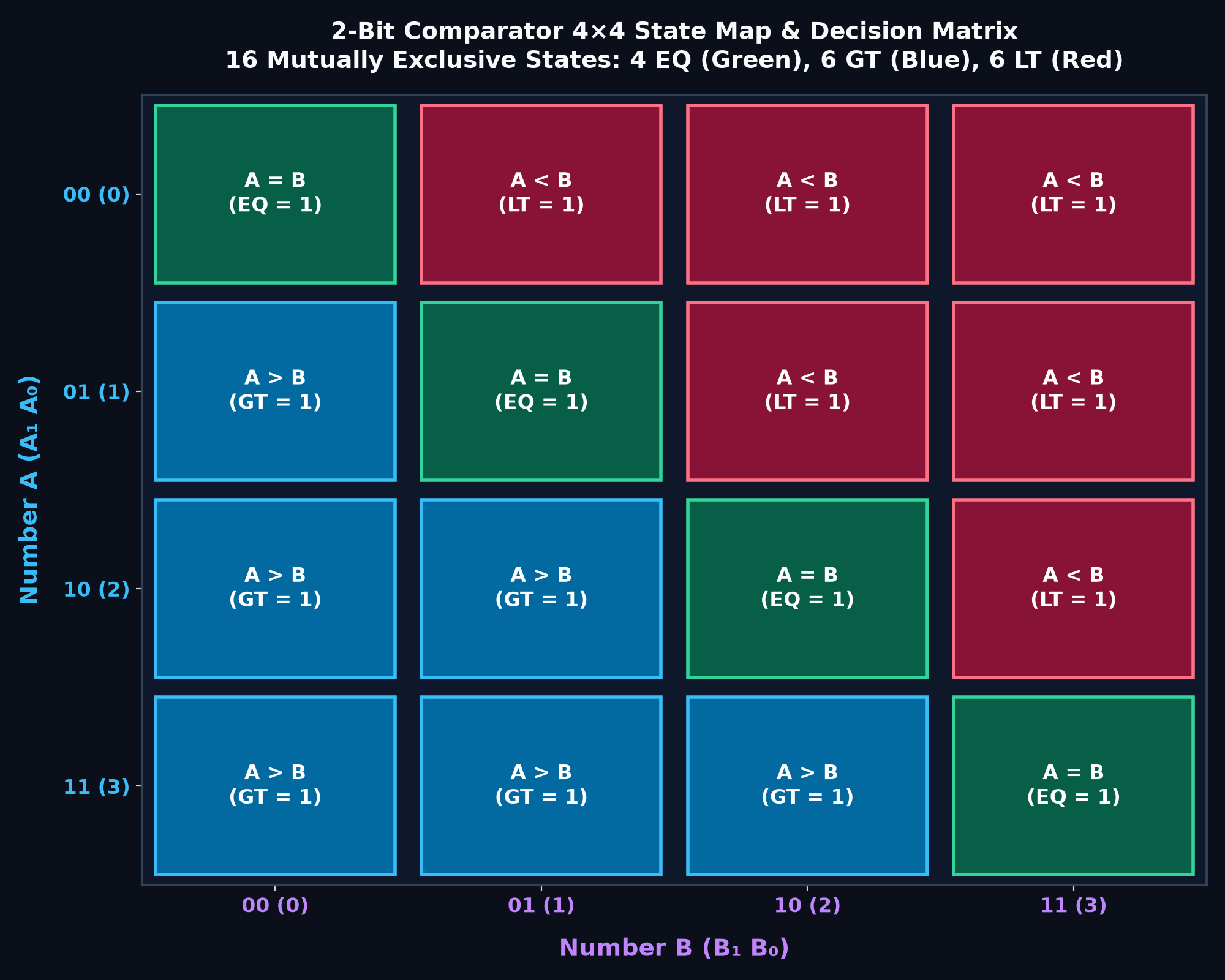
State Distribution in the 4×4 Decision Matrix
Plotting the 16 combinations as a 4×4 grid (Figure 1) highlights the structural symmetry of the circuit:
- Equality (
EQ): Exactly 4 states lie along the main diagonal (0-0,1-1,2-2,3-3), representing4 / 16 = 25%of all possible cases. - Greater-Than (
GT): Exactly 6 states occupy the lower triangular region (1>0,2>0,2>1,3>0,3>1,3>2), representing6 / 16 = 37.5%of cases. - Less-Than (
LT): Exactly 6 states occupy the upper triangular region (0<1,0<2,0<3,1<2,1<3,2<3), representing6 / 16 = 37.5%of cases.
---
4. Systematic Boolean Equation Derivation
Rather than constructing an unwieldy 4-variable Karnaugh map, digital comparators are derived hierarchically based on bit significance:
4.1 Equality Output (`EQ`)
Two binary words are equal if and only if each individual bit matches its corresponding counterpart. The standard logic function that tests equivalence between two single bits is the Exclusive-NOR (XNOR) gate:
- For bit 1:
E₁ = NOT(A₁ ⊕ B₁) = A₁ · B₁ + NOT(A₁) · NOT(B₁) - For bit 0:
E₀ = NOT(A₀ ⊕ B₀) = A₀ · B₀ + NOT(A₀) · NOT(B₀)
Overall equality requires both bits to match simultaneously:
EQ = E₁ · E₀
This requires two XNOR gates and one 2-input AND gate.
4.2 Greater-Than Output (`GT`)
Comparing two binary numbers proceeds hierarchically from the Most Significant Bit (MSB) to the Least Significant Bit (LSB):
1. MSB Dominance: If A₁ = 1 and B₁ = 0, then A is strictly greater than B regardless of A₀ and B₀. This produces the first product term: Term₁ = A₁ · NOT(B₁).
2. LSB Tie-Breaker: If the MSBs are identical (E₁ = 1), the decision falls to the LSBs. A is greater than B only if A₀ = 1 and B₀ = 0. This produces the second product term: Term₂ = E₁ · (A₀ · NOT(B₀)).
Combining both terms through an OR gate yields the complete expression:
GT = (A₁ · NOT B₁) + (E₁ · A₀ · NOT B₀)
4.3 Less-Than Output (`LT`)
By exact mathematical symmetry:
1. MSB Dominance: If A₁ = 0 and B₁ = 1, then A is strictly smaller than B. This produces the first term: Term₃ = NOT(A₁) · B₁.
2. LSB Tie-Breaker: If the MSBs are identical (E₁ = 1), A is smaller if A₀ = 0 and B₀ = 1. This produces the second term: Term₄ = E₁ · (NOT(A₀) · B₀).
Combining both terms through an OR gate yields:
LT = (NOT A₁ · B₁) + (E₁ · NOT A₀ · B₀)
---
5. Gate-Level Circuit Architecture and Verification
The complete circuit schematic implements these equations using standard 2-input logic gates arranged in 3 parallel functional lanes:
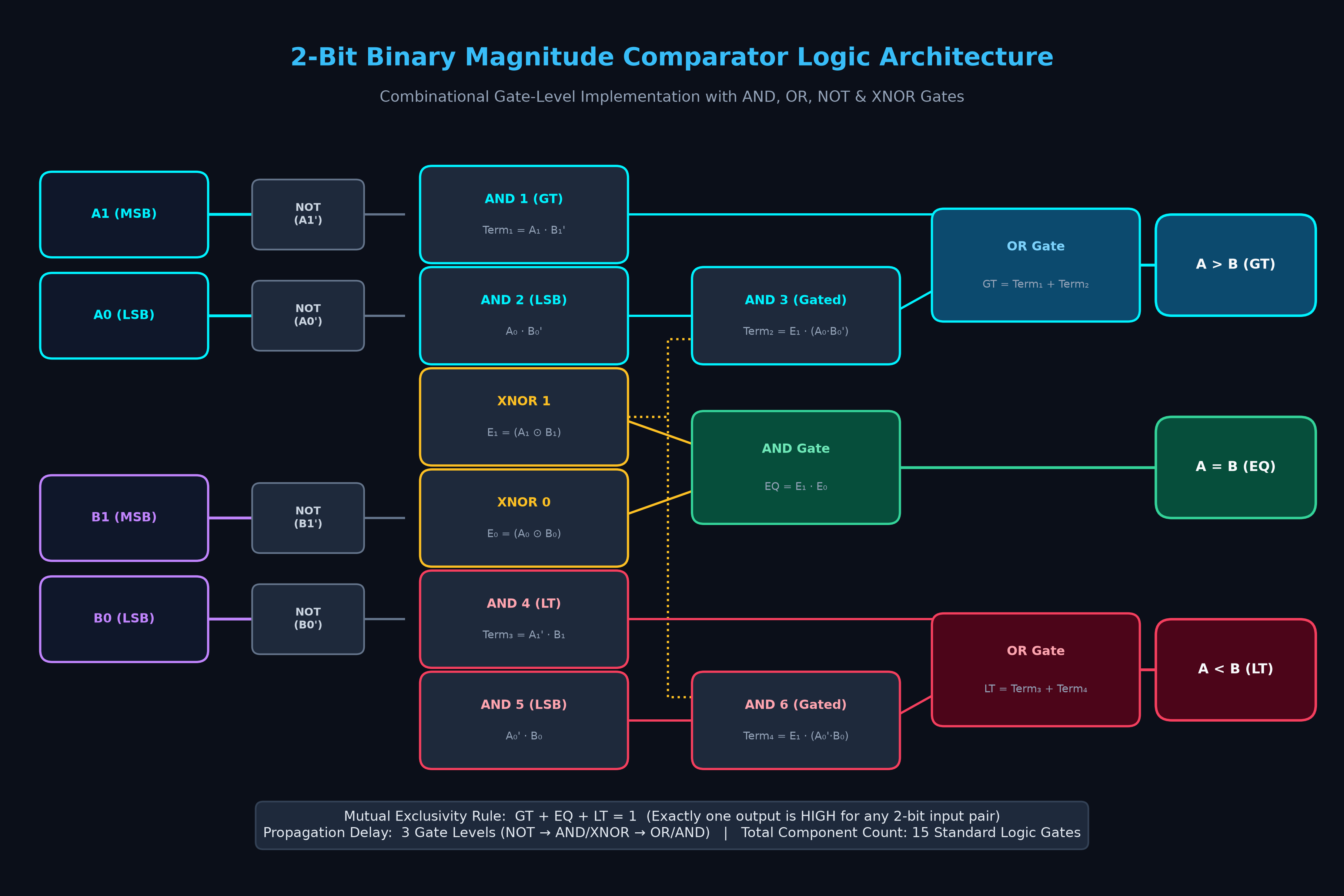
Component Breakdown and Gate Count
The gate-level schematic and CircuPilot simulation model utilize exactly 15 logic gates:
| Functional Block | Specific Gates Used in Circuit | Gate Count | Function in Architecture |
|---|---|---|---|
| Input Inverters | NOT_A1, NOT_A0, NOT_B1, NOT_B0 | 4 NOT | Generates inverted bit terms A₁', A₀', B₁', B₀' |
| Bit Equivalence | XNOR1, XNOR0 | 2 XNOR | Computes bit equivalence E₁ = (A₁ ⊙ B₁) and E₀ = (A₀ ⊙ B₀) |
| Equality Flag | AND_EQ | 1 AND | Computes overall equality EQ = E₁ · E₀ |
| MSB & LSB Products | AND_GT1, AND_A0_nB0, AND_LT1, AND_nA0_B0 | 4 AND | Computes raw bitwise comparisons A₁·nB₁, A₀·nB₀, nA₁·B₁, nA₀·B₀ |
| Gated LSB Terms | AND_GT2, AND_LT2 | 2 AND | Enables LSB comparison only when MSBs match (E₁ · (...)) |
| Output Summing | OR_GT, OR_LT | 2 OR | Sums MSB dominance and gated LSB terms for GT and LT |
| Total Component Count | Standard 2-input combinational gates | 15 Gates | Complete 2-bit magnitude comparator |
Logic Levels and Path Depths
Because CircuPilot's standard DC Operating Point analysis evaluates steady-state voltages rather than dynamic transient waveforms, timing performance is characterized by counting logic levels (gate depths):
EQOutput Path: Travels throughXNORandAND= 2 Logic Levels.GTandLTMSB Paths (Term₁,Term₃): Travel throughNOT,AND, andOR= 3 Logic Levels.GTandLTGated LSB Paths (Term₂,Term₄): Travel throughNOT,AND (raw LSB),AND (gated with E₁), andOR= 4 Logic Levels.
In discrete hardware families (such as 74HC CMOS operating at 5.0 V with typical 9 ns to 12 ns gate propagation delays under 50 pF load), a 4-level path typically exhibits approximately 30 ns to 40 ns of worst-case propagation delay before all outputs stabilize.
---
6. Applications in Computing: CPU Branching and Signed vs. Unsigned Arithmetic
Magnitude comparators are core architectural blocks in computer processors, though their role depends heavily on data representation:
6.1 Unsigned vs. Signed Comparison in ALUs
This circuit performs unsigned magnitude comparison, treating numbers as positive values from 0 to 3. In real-world microprocessors, comparison instructions (CMP A, B) must support both signed and unsigned comparisons:
- Unsigned Comparisons: Instructions such as
BHI(Branch if Higher) orBLO(Branch if Lower) evaluate pure magnitude, where relative order is reflected by the Carry flagC. - Signed Two's Complement Comparisons: When numbers represent signed integers (where a 2-bit word represents values from
-2to+1), a simple magnitude comparator is insufficient because the MSB acts as a sign bit. In ALU architectures, signed less-than evaluation (BLT) is determined by evaluating status register flags:
Signed Less Than = N ⊕ V
Here, N is the Negative flag (MSB of the subtracted result) and V is the two's complement Overflow flag.
6.2 Hardware Applications
1. Conditional Branching: In RISC architectures, comparator outputs feed directly into instruction decode logic to alter the Program Counter (PC).
2. Memory Address Decoders: Memory management units (MMUs) monitor address buses to ensure an accessed address falls within valid physical bounds: (ADDR ≥ BASE_ADDR) AND (ADDR < LIMIT_ADDR).
3. Hardware Sorting Networks: High-throughput graphics pipelines and DSPs deploy parallel arrays of comparators to execute median filtering and rasterization depth tests.
---
7. Scaling to Commercial ICs: The 74HC85 4-Bit Comparator
For physical printed circuit boards, building comparators from discrete gates is superseded by integrated medium-scale integration (MSI) devices.
The 74HC85 is an industry-standard 4-bit magnitude comparator. To compare 8-bit, 16-bit, or 32-bit words, multiple 74HC85 ICs are cascaded using three expansion inputs:
I(A > B): Cascading input for Greater-Than from a less-significant stage.I(A = B): Cascading input for Equal from a less-significant stage.I(A < B): Cascading input for Less-Than from a less-significant stage.
When cascading multiple chips, higher-order stages evaluate their 4 bits first. Only when the higher-order bits are identical (EQ = 1) do the expansion inputs enable the decision of the lower-order stages to pass through to the final outputs.
---
8. Common Design Mistakes and Debugging Tips
1. Inverting bit priority: Evaluating LSBs before MSBs causes severe logic failures (such as declaring binary 01 greater than 10 because bit 0 of the first word is 1). Always ensure that LSB conditions are gated by the higher-order equality signal (E₁).
2. Floating simulator nodes in SPICE: In behavioral SPICE simulation, unconnected output pins can cause matrix convergence warnings. In CircuPilot, each logic gate features internal RC low-pass networks to break algebraic loops in feedback circuits, but terminal output pins (GT, EQ, LT) should always connect to a load, voltmeter probe, or pull-down resistor to ground. Read more in our guide on why SPICE simulation fails on floating nodes.
3. Overlooking transient glitches: If observing comparator outputs on high-speed oscilloscopes, do not mistake brief nanosecond transition hazards for steady-state Boolean errors. Sample comparator outputs synchronously with clock edges after the longest logic level delay has elapsed.
---
Summary & Next Steps
Constructing a 2-bit magnitude comparator demonstrates how digital decision-making is structured from Boolean gates:
- XNOR gates detect bit-level equivalence.
- AND gates establish hierarchical significance from MSB to LSB.
- In steady-state equilibrium, the 16 possible states resolve into exactly 4 equality conditions, 6 greater-than conditions, and 6 less-than conditions.
- Exactly one output is asserted in steady state, guaranteeing logical consistency.
Explore the Interactive Circuit
You can interactively toggle input bits, inspect probe voltages, and verify all 16 states directly in CircuPilot:
- Launch Interactive 2-Bit Magnitude Comparator in CircuPilot →
- Explore our tutorial on logic gate simulation and truth tables →
- Explore our tutorial on building a 4-bit binary adder with logic gates →
Frequently asked questions
What is a 2-bit magnitude comparator?
A 2-bit magnitude comparator is a combinational digital logic circuit that compares two unsigned 2-bit binary numbers A (A1 A0) and B (B1 B0). In steady state, it produces three mutually exclusive active-HIGH outputs: A > B (Greater Than), A = B (Equal), and A < B (Less Than). Exactly one output settles at HIGH (approx 4.99V) for any valid input pair.
How does a comparator determine if A is greater than B?
A digital comparator prioritizes the Most Significant Bit (MSB). If A1 is 1 and B1 is 0, A is immediately greater than B regardless of the least significant bits (A1 · NOT B1). If the MSBs are identical (E1 = 1), the circuit checks the LSBs: A is greater if A0 is 1 and B0 is 0 (E1 · A0 · NOT B0). The overall equation is GT = (A1 · NOT B1) + (E1 · A0 · NOT B0).
What is the truth table of a 2-bit comparator?
With two 2-bit inputs, there are 2⁴ = 16 possible input combinations. The truth table yields exactly 4 states where A = B (when inputs are 00-00, 01-01, 10-10, 11-11), 6 states where A > B (01>00, 10>00, 10>01, 11>00, 11>01, 11>10), and 6 states where A < B. In steady state, the outputs are always mutually exclusive (GT + EQ + LT = 1).
What is the difference between an unsigned magnitude comparator and signed CPU comparison?
An unsigned magnitude comparator treats bit patterns as pure positive integers from 0 to 3. In signed two's complement comparison (such as in CPU ALUs), numbers include positive and negative ranges (-2 to +1 for 2 bits), and the less-than condition is determined by status register flags (specifically N XOR V, where N is the negative flag and V is the two's complement overflow flag), rather than pure magnitude logic alone.
Can I simulate a 2-bit comparator online with SPICE?
Yes. CircuPilot provides browser-based digital and mixed-signal SPICE simulation. You can wire logic gates (AND, OR, NOT, XNOR), connect interactive logic toggles, and inspect digital probe voltages in real time without installing desktop software.